
- How to connect a display to U8g2 Library?
- U8g2 full buffer, page buffer and u8x8 mode
Identify the display
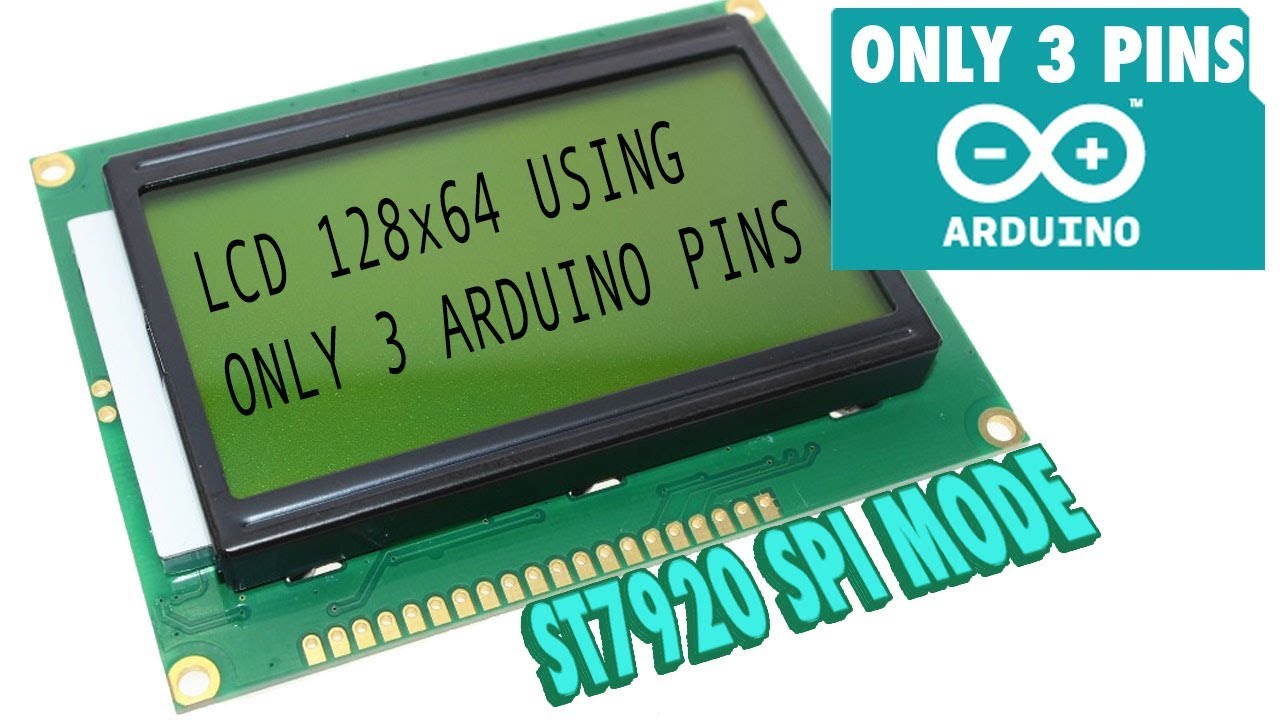
You need to know the controller and the size of your display (Note: 'Controllerless'displays are not supported by U8g2).In this example, we will use a ST7920 128x64 display. It has a ST7920 controllerwith a 128x64 LCD .
For U8g2 you have to select a matching constructor for the correct initialization ofthe display. Select a constructor from this page:C++ Setup/Arduino Constructor List
Often the constructor is also mentioned in the examples. But you may need touncomment the matching constructor.
The ST7920 GLCD is graphica and character mixed mode display. ST7920 LCD controller/driver IC can display alphabets, numbers, Chinese fonts and self-defined characters. It supports 3 kinds of bus interface, namely 8-bit, 4-bit and serial. Great Cow BASIC is currently supports 8-bit only. Home » Source Code » ST7920 driver 128. 64 LCD serial and parallel program can be downloaded directly. » 12864中文串口程序.c. Description: ST7920 driver 128. 64 LCD serial and parallel program can be downloaded directly related to the use of additional data interpretation.
For this example, locate the ST7920 128x64 section.
Select a physical bus
Graphics information has to be sent to the display. This information is received bythe display controller through a physical bus (usually two or more data lines),
a communication protocol and a command sequence. Often a display supports morethan one physical bus. You have to select and setup the correct bus.
The physical bus is selected by connecting special pins to GND (Low) or +5V (High).This SSD1306 oled, the PCB has several solder pads (labeled as BS0, BS1 and BS2)to setup the physical bus:
A small table on the left side gives hints about what setting will setup which bus.Typically the busses are:
- 3SPI, 3-wire SPI: Serial Peripheral Interface with three signals: Clock, Data and Chip-Select.
- 4SPI, 4-Wire SPI: Same as 3SPI, but with one additional line for commands and data (often labeled as D/C, RS or A0)
- I2C, IIC or TWI: Inter-Integrated Circuit Bus which has two signals: Clock (SCL) and Data (SDA).
- 8080: A 8-Bit bus which requires 8 data lines, chip select and a write strobe signal.
- 6800: Another 8-Bit bus, but with a different protocol.
At this point of time, it is often a good idea to read the datasheet of the displaycontroller or the manual for your display for instruction on how to setup a specificbus.
Sometimes the bus is just fixed and can not be changed. For this oled withSSD1306 controller nothing can be changed:
The type of the bus can be guessed from the number of pins and their lables. Inthis case, it seems to be a I2C bus because of the SCL and SDA lables.
For our initial example the PCB looks like this:
According to the ST7920 datasheet, the PSB pin selects between the 8-Bit and theserial (SPI) bus. For the serial bus, pin 'RS' is 'Chip-Select', pin 'E' willbe the clock input and pin 'RW' acts as data line.
Note: In the picture, PSB is connected to BLK, which in turn is connected to GND.This will select the serial bus for the ST7920 display.
Identify digital lines
The display must be connected to the Arduino board in order to transferdata from the Arduino board to the display. Depending on the selectedphysical bus, several pins have to be connected to the outputs of theArduino board.
In general, U8g2 can use any outputs of your Arduino Board.So it does not matter which output pin is used (However it might be cleverto select specific pins for hardware accelerated bus communication).
My suggestion is to write down the wiring. Here is the example for the ST7920 display.
| Display Pin | Arduino Pin Number |
|---|---|
| E, Clock | 13 |
| RW, Data, MOSI | 11 |
| RS, Chip Select | 10 |
| RST, Reset | 8 |
Note: RS (as labled on the PCB) actually means 'Register Select', however for SPI mode the RS pin becomes 'Chip Select'.
Remember to connect PSB pin with GND. Also apply correct voltage to the V0 inputfor this type of display (see datasheet).
U8g2 initialization
U8g2 needs to know which output pin is connected to which input of the display:The pin numbers are provided as list of arguments to the U8g2 constructor.The position within the list is important and indicates the function/purposeof the pin.
From the table here, the constructorhas the following template (with u8g2 as object name):
After something which is called 'rotation', the constructor expects the pin numberfor the clock line, the data line and the chip select line (cs). The resetline can be provided optionally.
The examples include similar constructor calls. You can uncomment one of themand update the pin numbers, if required:
A complete example will look like this:
U8g2 supports three different drawing modes:
- Full screen buffer mode
- Page mode (This is the U8glib picture loop)
- U8x8, character only mode
Full screen buffer mode
Pros and Cons
- Fast
- All graphics procedures can be used
- Requires a lot of RAM
Setup
Use the U8g2 constructor from here. The constructormust include the 'F' character. For example:
U8G2_ST7920_128X64_F_SW_SPI(rotation, clock, data, cs [, reset])
Usage
- Clear the buffer with u8g2.clearBuffer().
- Draw something with the usual draw commands.
- Send the buffer to the display with u8g2.sendBuffer().
Example
Page buffer mode (Picture Loop)
Pros and Cons
- All graphics procedures can be used
- Only a little bit of RAM is required
- Slow
Setup
Use the U8g2 constructor from here. The constructormust include the '1' or '2' character. For example:
U8G2_ST7920_128X64_1_SW_SPI(rotation, clock, data, cs [, reset])
Usage
- Call u8g2.firstPage().
- Start a do-while loop
- Inside the loop-body: Draw something with the usual draw commands.
- Loop as long as u8g2.nextPage() returns true.
Note: Always create the same picture inside theloop body. See details here.
Example
U8x8 character mode
Pros and Cons
- Fast
- No RAM required
- No graphics possible
- Not available for all displays
Setup
Use the U8x8 constructor from here. For example:
U8X8_ST7565_EA_DOGM128_4W_SW_SPI u8x8(clock, data, cs, dc [, reset])
Usage
All draw commands directly write to the display.
Example
≡ PagesFavoritedFavorite10Introduction
Welcome to the hookup guide for the Serial Graphic LCD Backpack. In this tutorial, you will learn how to use the backpack to its full potential. We'll start with the basic hardware overview, then move on to hooking the backpack up to a microcontroller. By the end, you should know all the capabilities of the backpack and how to implement them with any host device.
Suggested Reading
Before reading this hookup guide, you should be familiar with the following topics in order to get the most out of this tutorial. Please have a look if any of these concepts are unfamiliar to you.
Backpack Overview
The Serial Graphic LCD backpack was designed to provide a simple, serial interface for large, graphic liquid-crystal displays (LCDs). Besides writing text, the backpack allows the user to draw lines, circles and boxes, set orreset individual pixels, erase specific blocks of the display, and control the backlight. There's also a reverse mode that swaps the colors of the pixels and the background.
Although SparkFun sells the backpack individually, it is also sold with the 128x64 pixel Graphic LCD and the 160x128 pixel Graphic LCD. For the purposes of this tutorial, we will be using both of these LCDs to demonstrate the functionality of the backpack.
The backpack is controlled with an ATmega168 microcontroller running at 5V/16MHz. This product is primarily intended for embedded applications, but it can easily be connected to a computer and written to with a terminal emulator. Both methods will be covered in this tutorial.
Power Requirements
Voltages of up to 7V may be used to power the backpack, however, care should be taken to reduce the backlight duty cycle in such cases to reduce the chance of overloading the voltage regulator on the backpack. To avoid complication with the voltage regulator, it's best to power the backpack at 6V. You can also get away with powering the backpack from another 5V source. Keep in mind that anything below 5V will result in issues with the backlight and/or the display. If you are powering the backpack from a computer USB port or a microcontroller, make sure the output is actually 5V and not something like 4.5V.
Other Hardware Features
Contrast Potentiometer
There is a small potentiometer on the backpack that allows for contrast adjustments. This should already be adjusted for you, but if text is not readily apparent or otherwise does not suit your needs, feel free to adjust to your liking. If at anytime the text on your LCD becomes unreadable, ALWAYS check the contrast potentiometer first. It is very sensitive, and, if it gets bumped, even just slightly, it can throw off the contrast of the LCD making it unreadable.
Solder Jumper
There is a solder jumper on the backpack that determines which display is used. When the solder jumper is closed, code for the 128x64 display will run. If the jumper is open, code for the 160x128 display will run. This jumper is soldered during production according to which LCD the backpack is being attached. However, if you wish to use the backpack with your own LCD, you may need to handle this jumper accordingly.
TX Line
The TX line from the backpack has been left in the final design for future code revisions, debugging and user development, but it is not currently utilized as of this writing.
LCD Overview
Let's briefly discuss how these LCDs operate in order to better understand how the firmware we will be using later in this tutorial works. First, let's talk about how the pixels on the LCDs are mapped out.
The graphic LCD is mapped out in Cartesian coordinates as shown in the following picture:
Or, if you are using the 64x128 pixel LCD, it's more like this:
ASCII characters are printed to the screen withrespect to two user-changeable settings, x_offset andy_offset. These two settings define the top-left cornerbit of a character space, which is 6x8 bits. Bychanging x_offset and y_offset, the user can place testanywhere on the screen.
Printing characters to the screen happens left to right,top to bottom, without adjusting x_offset and y_offset.Further, changing the offsets will change the entireframe of the text, meaning that writing to the end ofone line and onto the next will happen seamlessly asthe text has no predefined locations where it can orcan't be written (except for locations close to the leftand bottom edges of the display).
Backspace is also functional and tries to maintain thereference frame as set by the user.
ASCII Commands
The Graphic Serial LCD Backpack is designed to be controlled by a variety of means. One of which is through a serial terminal. This can be useful if you want to use a personal computer as your control device. You can also send commands to the backpack in real time using the ASCII commands. This is useful for testing the LCD before embedding it into a project. Here is a full list of the ASCII commands.
Note: There are several instances where you will need to send ASCII values that require certain, unusual key presses. Anywhere you see < control someValue >, this means that you have to press both the Control key and that character on your keyboard at the same time. If you are using a Mac, some of these commands need to be issued in a slightly different manner. For any command that doesn't work using control, try using the unicode version of that character.
All commands are preceded with “ ”, or ASCIIdecimal 124 (0x7C). This tells the display that a commandsequence follows. Before any of the followingcommands are given, they must be preceded with “ ”.The actual character “ ” is not (and cannot be) printedto the screen.
Clear Screen
Sending “
Demo Mode
Sending “
Reverse Mode
Sending '
Splash Screen
Sending “
Set Backlight Duty Cycle
Sending “
Change Baud Rate
Sending “
| Character | Baud Rate |
| '1' | 4800 |
| '2' | 9600 |
| '3' | 19200 |
| '4' | 38400 |
| '5' | 57600 |
| '6' | 115200 |
As an example, to set the baud rate to 19,200bps,send 0x7C 0x07 0x33, or from a keyboard send “ ”,
In a pinch, the baud rate can be reset to 115,200.During the one second delay at power up, send thedisplay any character at 115,200bps.
Set X or Y Coordinates
Sending “
Set/Reset Pixel
Sending “

Draw Line
Sending “
Draw Circle
Sending “
Draw Box
Sending “
Erase Block
Sending “
Example 1 - FTDI Basic
Now that we know the commands used to control the LCD, why don't you give it a shot. In this example, you will be using an FTDI Basic to communicate with and control your LCD.
What You Will Need
- Either the 128x64 pixel Graphic LCD or the 160x128 pixel Graphic LCD
- FTDI Basic - 5V or FTDI Cable
Hardware
The simplest and fastest way to connect and print to the LCD is to use an FTDI Basic or FTDI Cable. Using jumper wires, connect the FTDI to the LCD like so..
| FTDI | Graphic LCD |
| 5V | Vin |
| GND | GND |
| TXO | RX |
Once you have the the LCD wired up correctly, plug the FTDI device into your computer. Open a terminal window. Make sure you have the correct settings: Baud: 115200, 8-N-1-NONE. Once you are connected, begin typing. Everything you type should now show up on the LCD! Refer back to the ASCII Commands section to see which keys you need to press to perform specific commands such as clearing the screen, drawing a circle, or printing text to a specific x,y coordinate.
Talking to the LCD from the computer is fun and all, but the real fun begins when you can print information to the LCD from and embedded device. In the next example, we'll use an Arduino to print information to the LCD.
Firmware Overview
Before we dive into hooking up the LCD to an Arduino, let's discuss the firmware for a minute. The firmware is the code that resides on the backpack. It serves as a bridge, or translator, between the LCD and whichever microcontroller you use to communicate with it. On top of the firmware, we've written an Arduino library to make using the backpack even easier.
Backpack Firmware
We've revamped the firmware that ships with the backpack. It runs smoother than ever to give any project an awesome graphical display. Pending you don't need anything too fancy, you should be able to use the default firmware for all your LCD needs. But that doesn't mean that it's not worth understanding. To see the firmware, head on over to the Serial Graphic LCD Backpack GitHub repository. You can either download the zip file, clone the repo to your computer, or just navigate with GitHub's default editor.
Inside the Firmware folder you'll see a lot of .c and .h files. These are the files that tell the backpack how to interact with the LCD based upon the input received. Since modifying the source code is beyond the scope of this tutorial, we'll leave it here. Just know that if there is some internal functionality that you'd like to add, delete, or modify, this is the place to do it.
Do note that you'll need a programmer to change the firmware on the backpack. It is not Arduino compatible, even though the IC on board is an ATmega328, the same IC found on many Arduino boards. Check out the Troubleshooting section for more info on how to reflash the firmware to your backpack.
Arduino Library
To make using the Serial Graphic LCD Backpack as easy as possible, we've written an Arduino library. The library can be found on the GitHub repository. This library basically creates function for each of the commands listed on the previous ASCII commands page. The example sketch that comes with the library demonstrates each function and shows you how to implement them for a full range of purposes on the LCD. If you need a refresher on installing an Arduino Library, please visit our Installing a Library tutorial.
Each function will be listed here and given a short description. However, these functions build upon the commands listed in the ASCII Commands section. For more details on each function, please refer to that section or read the comments provided in the library files.
Print Commands
printStr(char Str[78])- Prints a string to the LCD. The buffer is set to 78 by default but can be changed in the header file.printNum(int num)- Prints a single number to the LCD.nextLine()- Acts as a newline for text.
These three function exist because the instance of the Software Serial library is declared within the library files to communicate with the backpack. Therefore, using the typical serial.print() commands won't work to send text to the LCD while using this library.
LCD Functionality
clearScreen()- Clears the LCD of any and all pixels.toggleReverseMode()- Toggles reverse mode -- blue on white for the 160x128 display and green on black for the 128x64 display.toggleSplash()- Turns the SparkFun splash screen on or off. Note that the one second delay on startup remains with or without the splash screen enabled.setBacklight(byte duty)- Set the brightness of the backlight. Takes a single int as a parameter. The range is 0-100, where 0 is OFF and 100 is full brightness. Anything higher than 100 will still result in a max value of 100.setBaud(byte baud)- Set the baud rate of the backpack. Takes a single int as a parameter with a range of 49-54.restoreDefaultBaud()- Restores the LCD back to the default baud rate of 115200bps.
Cursor Positioning
setX()- Sets the x position of where text will appear on the screen.setY()- Sets the y position of where text will appear on the screen.setHome()- Sets poth x and y back to position 0,0.
Drawing
setPixel(byte x, byte y, byte set)- Set or reset (revert back to the background color) any pixel on the LCD.drawLine(byte x1, byte y1, byte x2, byte y2, byte set)- Draws a line between two x,y coordinates.drawBox(byte x1, byte y1, byte x2, byte y2, byte set)- Draws a box between two x,y coordinates.drawCircle(byte x, byte y, byte rad, byte set)- Draws a circle with the center point starting at the given x,y coordinate and then extends out to the given radius.eraseBlock(byte x1, byte y1, byte x2, byte y2)- Erases the block spanning from the two given x,y coordinates.demo()- Initiates an internal demo built into the firwmare.
Example 2 - Arduino
We'll first go over the quick and easy way to print to the LCD from an Arduino, then we'll go over a more robust method that utilizes the special characters built into the LCD's firmware.
Download virtual dj pro 7 for free. Audio & Video tools downloads - VirtualDJ Pro Full by Atomix Productions and many more programs are available for instant and free download. Free download VirtualDJ Pro Full VirtualDJ Pro Full for Mac OS X. VirtualDJ Pro Full - With VirtualDJ's breakthrough BeatLock engine, songs will always stay in beat, and the DJ works their mixes incredibly faster than they ever could. Download virtual dj pro le free for mac.
What You Will Need
- Any Arduino compatible board - we recommend the RedBoard or an Arduino Uno.
- Either the 128x64 pixel Graphic LCD or the 160x128 pixel Graphic LCD
- The appropriate USB cable for your Arduino
Serial Pass-through
This first example utilizes the built in UART on the Arduino. By doing this, we have to be careful when uploading code to the Arduino while the LCD is connected, since they'll be sharing the same lines. We're going to do things slightly backwards, and upload the code first, then connect the LCD.
With just a few lines of code, you can pass text through the Arduino to a terminal window. Copy this code to a new sketch, and upload it to the Arduino.
This code takes whatever the Arduino receives on its RX line and sends it back out the TX line to the Serial Graphic LCD. You must use Serial.write() instead of Serial.print if you wish to see characters on the LCD and not ASCII numbers.
Hardware
Now, connect the LCD to the Arduino like so.
Make sure your connections are as follows:
| Arduino | Graphic LCD |
| 5V | Vin |
| GND | GND |
| TX | RX |
You don't need to hook up to the LCD's TX line because you're only sending data to the LCD.
Now, open a terminal window (again at 115200), and begin typing. Again text should appear on the LCD. Backspace still works too!
Arduino Library Example
In this last example, we're going to use the Serial Graphic LCD library to do all the work for us. One important feature of the library is that it uses the Software Serial library to create an alternative serial port for the Arduino to communicate to the LCD. The problem with the previous example is that we are using the internal UART and thus have to disconnect the LCD every time we want to upload code. This can be a pain in the butt when you are developing code and need to upload several times.
Hardware
We can use the previous examples setup for this example, you'll just need to change one jumper wire. Move the jumper wire connected to the Arduino's TX pin to Digital Pin 3 on the Arduino. This is the pin that the Serial Graphic LCD library uses when it initializes the Software Serial library.
Your connections should look like this now:
| Arduino | Graphic LCD |
| 5V | Vin |
| GND | GND |
| Pin 3 | RX |
Or, for the visually inclined, here's a picture of what your connections should look like.
Firmware
If you haven't done so already, download and install the Arduino library, or clone it to your computer. Head back to the Firmware Details section for more info on installing the library. Once it's installed, open up Arduino, and navigate to the library Example.
Select the proper serial port and board, and upload the example to your Arduino. Once uploading has finished, the library demo should begin. It will run through examples of using almost every function in the library. All that's left is to sit back and enjoy the show!
Troubleshooting
Display Issues
- If you don't see any letters, make sure the contrast potentiometer on the backpack is adjusted accordingly. You'll need a fine-tipped screwdriver to adjust it. Be careful when adjusting this trimpot as turning it too far or too hard can result in the trimpot breaking.
- Make sure you are giving the backpack at least 5V. Any lower and you may have an issue with contrast. Some USB ports run around 4.7-4.8V and may not have enough voltage to fully power the LCD and backpack. We recommend powering the LCD with 6-7V.
- If you can't see any letters, even when the contrast is adjusted accordingly, then there may be a baud rate issue. If you changed the baud rate and forgot to what you changed it, you can use the
restoreDefaultBaud()command in the Arduino library to restore the baud rate to its default of 115200bps. Simply create a sketch that imports the Graphic Serial LCD library and then call the restore function in Setup.
Copy and paste this code in to Arduino, make sure the LCD's RX pin is connected to digital pin 3 on the Arduino, and then upload. You should see the screen print 'Baud restored to 115200!'
Reflashing the Firmware
If you are experiencing odd behavior from your backpack, it may be the firmware. If this happens, we recommend updating the backpack with the latest firmware. We'll briefly describe how to do this yourself if you have the proper tools.
The latest version of the firmware can be found on GitHub. Visit the link to the repository. Clone the repository, or download the zip file. Remember the location of this file.
You're going to need some way to upload the firmware to the backpack. We recommend using an Atmel AVR MKII programmer. If you don't have an MKII, you could use something similar such as the Pocket AVR Programmer. Plug your programmer into your computer. You can also use an Arduino board as a programmer. For more info on this and general reflashing firmware information, please see our Installing an Arduino Bootloader tutorial.
In this example, I'm going to use Atmel AVR Studio (v4.18) to upload the .hex file to the backpack. You can also use AVRDude to accomplish the same task in the command line. If you are running Mac or Linux, you'll either need to look into uploading AVR code on your particular OS, or use a virtual machine such as Wine or VMWare to run AVR Studio in Windows.
Once you've figured out how to get AVR studio up and running, go ahead and start the program. You should be greeted with a prompt asking you to choose which programmer you're using. Select AVR MKII, or whichever programmer you're using.
Now, you're going to want to select to which chip you plan to upload. Select ATmega168P.
Click on the Program tab. In the 'Flash' section, click the button with three dots on it to browse for the hex file you downloaded from GitHub.
Browse for the .hex file that come with the GitHub download.
Once you have pointed AVR Studio to the hex file, connect the programmer to the ISP header on the backpack, and click 'Program.'
You should see a success message in the bottom of the program. If so, the new firmware should be on the backpack and ready to go!
Resources and Going Further
That about wraps it up. You should now have a good understanding of how the Serial Graphic LCD works and how you can use a variety of means to control the LCD. Now get out there and make some awesome projects with an nice user interface. For more info on the S-G-LCD backpack, check out the links below.
- Author: admin
- Category: Category